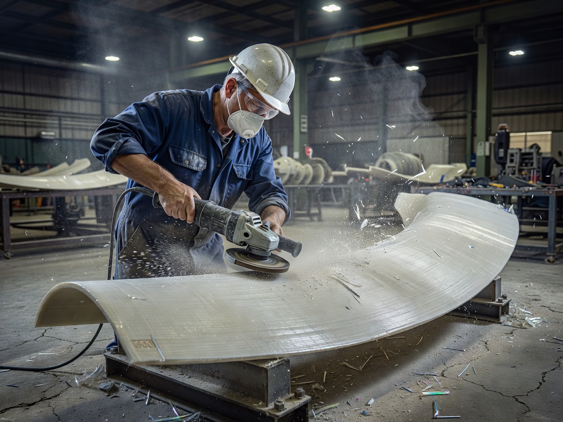
 Figure 2: Grinding step-lap scarfs on a glass-fibre polyester aerodynamic shell prior to epoxy resin vacuum consolidation.
The Fluid Dynamics of Leading Edge Erosion (LEE)
We are fascinated by the sheer physical violence occurring at the tips of modern turbine blades. When a 115-meter rotor rotates at 12 RPM, the outer 15% of the blade cuts through the atmosphere at linear speeds between 75 and 90 meters per second (upwards of 300 km/h). At this velocity, microscopic raindrops, airborne sand particles, and sea-salt aerosols behave like miniature ballistic impactors.
Over 2 to 5 years of operation, these continuous impacts degrade the top polyurethane gelcoat. As micro-craters coalesce, the erosion penetrates down into the underlying glass-fibre epoxy laminate layers. Aerodynamically, even a 0.5-millimeter roughness along the leading edge trips the laminar boundary layer prematurely into turbulent flow, degrading lift-to-drag ratios and sapping up to 4% of annual energy yield.
Leading Edge Protection (LEP): Coatings, Shells, and Tapes
Field engineering teams employ three primary remediation techniques depending on climate severity and site logistics:
- Polyurethane Topcoat Systems: High-build, multi-part elastic coatings cured in situ. They offer smooth geometric conformity but demand strict ambient temperature and relative humidity windows during up-tower rope-access application.
- Pre-Formed Polyurethane Shells: Factory-moulded elastomeric shoes bonded with specialized structural adhesives. They provide exceptional mechanical dampening against heavy hailstone impacts.
- Specialized LEP Tapes: Acrylic or polyurethane elastomer tapes backed with pressure-sensitive adhesives. Ideal for rapid up-tower field patching, though edge-sealing requires careful roller pressure to prevent delamination creep.
The Structural Box: Spar Caps and Shear Webs
While the outer aerodynamic shell forms the airfoil contour, the primary bending moments are resisted by internal spar caps (unidirectional glass or carbon fibre) and vertical shear webs (balsa or PVC foam cores sandwiched by biaxial laminate). When shear web adhesive fillets debond, the entire blade becomes susceptible to catastrophic buckling under sudden wind shear gusts.
Structural Adhesive Bond Line Inspection and Scarf Repairs
Turbine blade halves are traditionally joined along the leading and trailing edges using thick paste adhesives (such as toughened epoxies, polyurethanes, or vinyl esters). Over millions of deflection cycles, adhesive voids, incomplete wet-out, or thermal expansion mismatch can initiate cracks along the trailing edge bond line.
When repairing damaged composite laminates up-tower, technicians grind out the damaged plies using a stepped or bevelled scarf ratio—typically 1:30 or 1:50 for structural unidirectional carbon caps, and 1:20 for glass-fibre shell areas. Replacement fabric plies are precisely matched for fibre aerial weight, alignment orientation (0°, ±45°, 90°), and infused with low-viscosity resin under vacuum debulking blankets with thermostatically controlled silicone heating mats to achieve glass transition temperatures ($T_g$) matching factory autoclave standards.
Lightning Protection System (LPS) Continuity and Receptors
Due to their height and isolation, wind turbines are lightning attractors, absorbing dozens of direct strikes each season. The LPS consists of copper or tungsten alloy receptors positioned flush along the blade tip and mid-span, wired into a heavy internal down-conductor running through the root bearing to earth grounding rings.
Annual maintenance requires four-wire Kelvin micro-ohmmeter testing from tip receptor to hub root. If contact resistance rises above 0.2 ohms due to lightning arc pitting or internal conductor disconnects, the next strike will vaporize moisture inside the composite cavity, exploding the blade shell outward. Maintenance involves machining receptor pucks flush, cleaning carbon burn trails, and replacing degraded spark gaps.
| Damage Class | Visual Manifestation | Engineering Impact | Typical Remediation Window |
|---|---|---|---|
| Severity 1: Gelcoat Erosion | Surface pitting, pinhole voids | Minimal lift degradation (<0.5%) | Next scheduled summer campaign |
| Severity 2: Laminate Exposure | Glass fibres exposed, dry roving | 1.5% to 3.0% AEP loss, water ingress | Within 60 operational days |
| Severity 3: Core Delamination | Hollow sound on tap test, surface bulge | Structural buckling vulnerability | Immediate derating; fix within 14 days |
| Severity 4: Spar Cap Crack | Volumetric fissure in UD carbon/glass | Imminent total structural failure | Immediate physical rotor lock |
Aerodynamic Add-Ons: Vortex Generators and Serrations
Maintenance campaigns frequently encompass auxiliary aerodynamic components. Vortex generators (VGs)—small plastic triangular fins bonded on the suction side near the root—delay boundary layer stall. Serrated trailing edges (commonly called dino-tails) attenuate trailing-edge vortex shedding noise by 2 to 3 decibels, allowing operators to run turbines at full rated output without violating municipal acoustic curbs. Replacing detached VGs and verifying silicone bond adhesion restores designed boundary-layer performance.