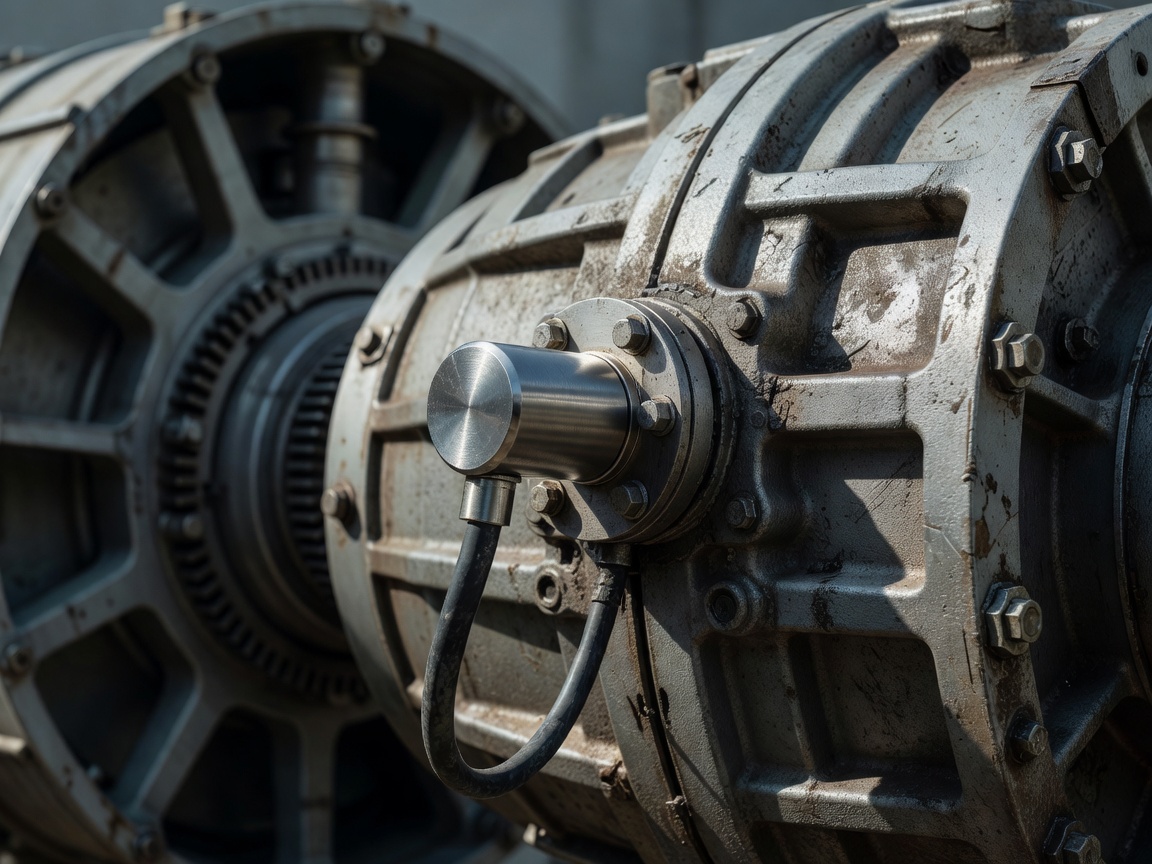
 Figure 5: High-frequency tri-axial piezoelectric accelerometer installed directly onto the planetary stage casing.
The Philosophy of Predictive Vibration Analysis
We view vibration condition monitoring as the acoustic stethoscope of the modern wind nacelle. Every spinning element—a ball bearing roller, an intermediate pinion tooth, or a generator rotor bar—generates a distinct kinetic frequency signature dictated by its physical geometry and rotational speed.
By installing high-sensitivity piezoelectric accelerometers at strategic mechanical transfer points (main bearing, planetary ring gear, intermediate shaft, and high-speed generator bearing housings), the CMS system continuously samples acceleration waveforms. Fast Fourier Transform (FFT) algorithms convert these time-domain vibrations into frequency spectra, pinpointing characteristic defect harmonics long before thermal rises occur.
Characteristic Bearing Defect Frequencies
When a roller bearing begins to fatigue, tiny spalls on the raceways create periodic mechanical shocks as rolling elements pass over the defect. We track four fundamental kinematic frequency markers:
- BPFO (Ball Pass Frequency Outer): Shocks produced as rolling elements traverse a defect on the stationary outer ring raceway.
- BPFI (Ball Pass Frequency Inner): Shocks produced on the rotating inner ring raceway, typically modulated by shaft running speed.
- BSF (Ball Spin Frequency): Rotational speed of the rolling elements themselves around their own center axes.
- FTF (Fundamental Train Frequency): Rotational speed of the bearing cage assembly, indicating cage pocket wear or guide ring friction.
Envelope Demodulation (High-Frequency Resonance)
Incipient roller micro-cracks produce minute, low-energy impulses that are normally masked by loud low-frequency aerodynamic rumble. High-frequency envelope analysis filters out base rotational frequencies, band-passes resonance zones (typically 5 kHz to 20 kHz), and rectifies the signal, revealing clean shock repetitions indicative of Stage 2 bearing degradation weeks ahead of failure.
Online Inductive Oil Debris Monitoring
Vibration monitoring is powerfully augmented by real-time lubrication condition sensors installed directly in the pressurized gearbox lubrication loop. Inductive coil sensors detect the passage of metallic particles through an electromagnetic field:
By measuring distortion phase and amplitude, the sensor differentiates between ferrous particles (steel gear chips or bearing flakes) and non-ferrous particles (bronze or aluminum cage fragments). A sudden spike in ferrous particle generation rates (>50 particles per hour >100 μm) serves as unambiguous confirmation that surface fatigue has progressed into active sub-surface delamination.
SCADA Temperature Trends and Operational Anomaly Detection
Standard Supervisory Control and Data Acquisition (SCADA) systems record 10-minute average, minimum, and maximum values across hundreds of digital channels. While 10-minute data lacks the granularity of 20 kHz vibration streams, it contains long-term thermodynamic truth.
We analyze relative temperature differentials ($\Delta T$) rather than raw values. For instance, comparing the generator rear bearing temperature against the ambient nacelle temperature under identical active power output curves exposes cooling fan degradation or grease breakdown months before the bearing reaches high-temperature trip thresholds (typically 85°C–95°C).
| Telemetry Channel | Sensor Modality | Sampling Frequency | Lead Time to Catastrophic Failure |
|---|---|---|---|
| Acoustic Emission (AE) | High-frequency piezo crystal | 100 kHz – 1 MHz | 6 to 12 months (Micro-crack formation) |
| Vibration Acceleration | IEPE Accelerometer | 10 kHz – 50 kHz | 2 to 6 months (Raceway spalling) |
| Inductive Oil Debris | Inline magnetic coil flux | Real-time pulse count | 3 to 8 weeks (Active flaking) |
| SCADA Thermocouple | PT100 RTD sensor | 10-minute aggregated | 1 to 3 weeks (Severe friction/seizure) |
Rotor Imbalance and Tower Resonance Detection
Structural condition monitoring extends beyond rotating internals to the whole tower. Dual-axis low-frequency accelerometers (0.1 Hz to 10 Hz) mounted near the tower top detect aerodynamic and mass rotor imbalance ($1P$ frequency harmonics) as well as blade pass harmonics ($3P$ for three-bladed rotors).
If a blade accumulates internal water ingress through a cracked adhesive bond line or experiences pitch calibration drift of merely 0.8 degrees, the resulting mass and aerodynamic eccentricity generates a strong $1P$ lateral tower oscillation. Flagging this signature early protects tower foundation bolts from cyclic fatigue damage.