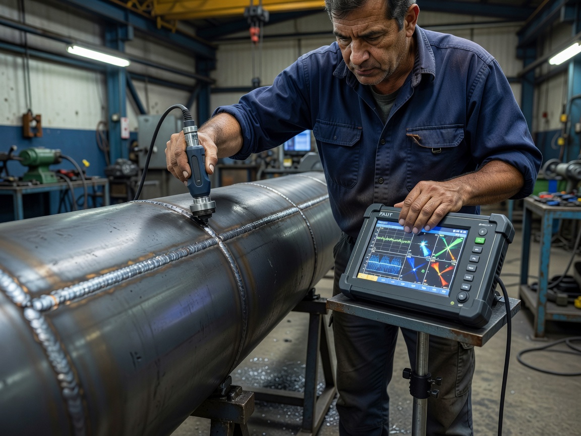
 Figure 1: Phased-array ultrasonic testing applied along tower section flange welds during a periodic structural recertification.
The Structural Hierarchy of Turbine Inspections
When we talk about utility-scale wind turbine inspection, we are not looking at casual walkthroughs. A modern 4 MW to 15 MW unit operates under relentless multi-meganewton thrust loads, cyclical torque reversals, and fluctuating aerodynamic shear. To maintain continuous mechanical certification, inspection campaigns must be structured into strict structural zones, each demanding specialized metrology.
Inspection planning begins at the foundation interface. On onshore installations, engineers examine the foundation pedestal, assessing grouting integrity between the steel base flange and the high-strength concrete slab. We inspect for radial micro-cracks, groundwater ingress, and anchor bolt relaxation. Each M36 to M48 anchor bolt must maintain precise pre-tension to prevent rocking moments from inducing cyclical fatigue in the sub-grade reinforcement cage.
Tower Weld Seams, Flanges, and Fastener Integrity
Rising vertically, steel tubular towers are fabricated in multiple cylindrical or conical can sections joined by internal circumferential L-flanges. Inspection teams employ phased-array ultrasonic testing (PAUT) and magnetic particle testing (MT) along longitudinal and circumferential submerged-arc weld lines.
Stress concentrations typically cluster around the lower third of the tower height, where dynamic wind buffet moments reach their apex. In addition to ultrasonic scan paths, technicians verify bolt torque marks across every flange ring. Using hydraulic torque wrenches and calibrated bolt-tension monitors, we sample bolt sets to confirm that relaxation has not occurred beneath constant cyclic vibration.
Key Non-Destructive Testing (NDT) Modalities
- Phased Array Ultrasonic (PAUT): Maps internal volumetric flaws, laminate voids, and weld root cracks without surface stripping.
- Eddy Current Testing (ECT): Evaluates conductive weld boundaries for fatigue crack initiation through protective paint layers.
- Thermographic Infrared Imaging: Flags frictional hot spots in yaw gears, electrical busbar junctions, and blade internal delaminations.
- Autonomous Optical Photogrammetry: Captures sub-millimeter surface features across all three rotor blades within a 45-minute hovering envelope.
Nacelle Bedplate and Mechanical Support Frame
Inside the nacelle housing, the cast-iron or welded-steel bedplate anchors the entire drivetrain. This structural backbone absorbs torque reaction forces from the planetary gearbox and generator stator. Our visual and dye-penetrant inspections zero in on high-stress node transitions: where the main bearing pedestal merges into the yaw drive deck.
Any microscopic fatigue propagation here can misalign the high-speed shaft coupling, destroying generator bearings in tens of operational hours. Technicians inspect the yaw drive ring teeth for flank wear, plastic deformation, and grease contamination, confirming that the multi-motor yaw brake assemblies provide uniform clamping pressure during extreme gusts.
Autonomous Aerial Drone vs. Rope-Access Inspection
The industry has undergone a technological evolution regarding exterior blade and shell assessment. Autonomous multi-rotor unmanned aerial vehicles (UAVs) equipped with telephoto lenses and RTK positioning can capture thousands of high-definition imagery frames in a single sortie. This enables rapid classification of leading-edge degradation and surface voiding across large fleets.
However, drones cannot perform tactile mechanical verification. When ultrasonic tap testing, internal root sleeve bolt ultrasonic checks, or composite core depth measurements are required, certified rope-access blade specialists (IRATA / SPRAT Level 3) remain indispensable. We view drone photogrammetry as the fleet-wide screening filter, and rope access as the precision surgical intervention team.
| Inspection Modality | Optimal Target Zone | Weather Dependency | Primary Defect Captured |
|---|---|---|---|
| Autonomous Drone Vision | External aerodynamic blade shell | Wind < 8 m/s, dry weather | Leading-edge pitting, gelcoat cracks |
| Phased Array Ultrasonic | Tower weld seams, spar caps | Sheltered / internal work | Sub-surface voids, weld root defects |
| Rope-Access NDT | Root transition, blade trailing edges | Wind < 10 m/s, zero rain | Adhesive bondline split, laminate delamination |
| Endoscopic Video Scope | Planetary gearbox internal gear teeth | Turbine stopped, shaft pinned | Micropitting, scuffing, roller spalling |
Inspection Documentation and Defect Severity Categorization
Collecting imagery is useless without standardized classification. We rely on standard five-tier engineering severity matrices: Category 1 (cosmetic paint abrasion) through to Category 5 (imminent structural compromise requiring immediate shutdown). Every finding ties back to component coordinates: spanwise meter markers on blades, clock positions on bearing raceways, and internal elevation markers along tower sections.
Correlating these inspection logbooks with SCADA vibration alarms closes the loop on asset health, giving engineering teams defensible criteria to schedule repairs during calm summer weather windows before winter gale seasons arrive.